Overhead Equipment – Overlaps
In electrical circuit, the series and parallel connections are made using junction box, twisted of cables together, soldering, brazing, etc.
This is not possible in case of overhead contact and catenary wire. Similar purpose in OHE is achieved through overlaps. Overlap is defined as an arrangement where two set of contact wire runs together in parallel for a short distance without any mechanical or electrical connectivity but facilitating smooth movement of pantograph over it. The two contact wires are either connected firmly by a jumper or an isolator/ interrupter. It is called un-insulated overlap when connected firmly and insulated when connected through a switch like isolator or interrupter. The need for the overlaps arises because of
- Restriction on the length of the conductor due to handling of weight, drum size, tension to restrict the sag and elongation due to temperature variation depends on length.
- Maintenance management of higher length is difficult for schedule replacement, kink attention etc.
- Separate tension length of loop line, yard lines, loco maintenance lines, etc.
- Segregation of section to minimize the faulty section to minimize the impact of fault on the running of trains.
Un-insulated Overlap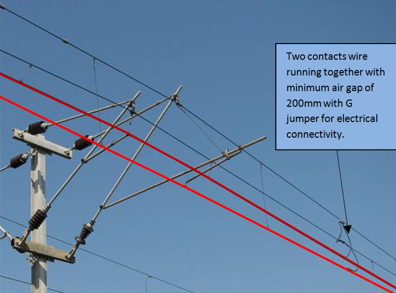
Un-insulated overlap is required when continuity of current flow is required between two conductors whose length is limited due to design considerations. The contact wire cannot be indefinitely long and a standard length of 1.6 Km is designed taking into consideration the thermal expansion, tension, weight, etc. This length is also called one tension length.
Two sets of conductors are separated by 200 mm & connected by a large jumper of 105 sq.mm. cross-section.
The overlap is either 3 or 4 span length. Three span length overlap is used when radius of curvature is more than 5000 m with span length more than 54 m and four spans with radius of curvature less than 5000 m with span length less than 54 m.
Un-insulated overlaps are provided for connectivity for two tensions lengths.
Insulated Overlaps
In Insulated Overlaps, the two sets of Conductors are separated by 500 mm in air. The gap is decided requiring the minimum air clearance for 25 kV. With this clearance, it is possible to make one length dead keeping the other energized by opening the switch that normally connects the two lines. The switch is either an isolator or interrupter. Isolator is operated manually where as interrupter by a command from remote center through SCADA. Insulated overlaps are preferred at the following locations
- At sub-sectioning and paralleling post (SSP) where two tension lengths are connected by an interrupter.
- OHE is sub-divided into different elementary sections between two SSP to facilitate minimum OHE isolation during fault condition.
- Yard, loop and maintenance lines
- Neutral Section

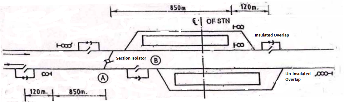
Section Isolator for Elementary sections at a Railway Station
Diagram below showing Section Isolator, Insulated and Un-insulated overlap at a Railway Station
See the current collection
this diagram isvery helpinig of new trd staf
unisulated overlap
Nice
Nivtral section ki jankari mast h.
TRD
All
Work handbook
Vej dia Sir ok
How many masts are there between OPEN DJ and CLOSE DJ boards in
an overlapping natural section.
Can u published this ohe book as given by customers
Sir I want to know about OHE foundation detail.