Electrical Protection System – Tap Changer Locomotive
Protection system of Tap changer locomotive is primitive based on the technology prevailing during 50s. This was imported along with WAG1 class of locomotive and continued to be followed with all class of locomotive developed later on. The protection system comprises of instantaneous relay detecting over current in AC and DC system. DC system is floating and any one fault results in tripping with provision of isolation of equipment or relay so that locomotive can work up to destination.
Tap Changer Electric Locomotive
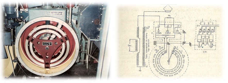
ET1 and ET2 The protection of the locomotive against surge voltage is secured by means of two roof surge arrestors with spark dischargers ET 1 (mounted on a support insulator of the HT Roof Bars) and ET 2 (mounted on the HT input terminal of the locomotive). are with air sparking gap of —-mm and discharge the surge voltage. Presently surge arresters are being provided. Instantaneous Over current Protection- High Voltage Overload Relay QLM The relay QLM is fed by means of the high voltage current transformer TFILM (250/5A) which causes the high voltage circuit breaker DJ to trip , if the current taken in by main transformer exceeds the setting value of the relay (300 A). The relay protects from over current drawn by 25kV system in the locomotive namely transformer, tap changer, roof bushing etc and also acts as a secondary protection for rectifier and traction motor. Relay is popularly called QLM relay. Initially, QLM was provided with auto-resetting mechanism wherein loco pilot can energize the locomotive. There were cases of fire on locos and investigation stated that loco pilot shall not energize the locomotive without inspection of HT compartment and this led to the modification of provision of manual resetting mechanism. Some of the Railways has decided not to permit resetting and accepts line failure of locomotive with a view that there will not be any transient tripping through safety relay QLM. Transformer: Transformer is filled with mineral oil. A secondary safety protection by way of pressure relief valve called safety vale is also provided. Any fault in the transformer, causes QLM tripping as well as safety value blowing. Most likely QLM is not acting as primary protection. On Line Tap Changer: There are 32 taps in tap changer popularly called GR for on line tap changing. GR is filled with mineral oil to prevent formation of arc during tap changing on load. This is very intensive duty equipment and any fault results QLM dropping and simultaneous blowing of safety value. Here also QLM not acting as primary protection. Tap changer is protected from sticking up in between notches and on notch by relay called Q44 and Q46. There are also directive that locomotive shall not be allowed to work with Q44 in wedged/packed condition as the most important protection to GR gets bypassed.
Photograph of Tapchanger and working sketch
Roof Bushing: Condenser bushing were provided in the initial design filled with mineral oil but any case of fault was resulting its bursting and oil throwing inside the HT compartment, making the locomotive vulnerable to fire. In the initial stage the oil was removed and later on replaced by cable head terminations.
With advancements in numerical protection system, Indian Railways shall consider provision of relay to augment the primary protection which presently is not sufficient.
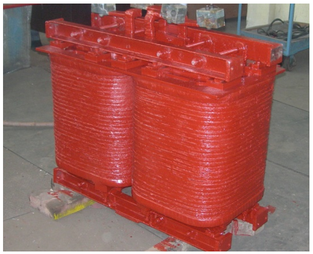
Instantaneous over current relay for Silicon Rectifies (QRSI 1 & 2) The relays QRSI 1-2 are fed by means of the rectifiers current transformer RSILM 1 and 2 (4000/5A) which cause the high voltage circuit breaker to trip, if the current taken in by the rectifiers exceeds the setting value of the relays (3600 A). This relay is provided to protect the rectifier block from over current and popularly called QRSI relay. Diodes in the rectifiers are also protected by HRC fuses. Rectifier is generally sturdy with minimum reliability issues, but the relay plays an important role in protecting the traction motor from over current as well. It protects smoothing reactor from over current as well, but it is the inter turn faults in smoothing reactor which is a cause of concern and no protection and has been responsible many cases of fire. This has been tackled by eliminating quality issues. Smoothing reactor causing fires on locos were observed even in the first batch of imported WAG1 locos.
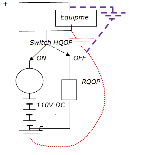
Earth Fault Relay for protection of 1500V power circuit for Traction Motor and associated circuit: relay is popularly called QOP. 750V DC circuit is floating potential and divided into two circuits consisting of one number rectifier block, smoothing reactor and three traction motors. In floating circuit, if there is one fault, nothing will happen because circuit is not complete but as soon second fault takes place; heavy fault current flows depending fault resistance. It results tripping through QOP, QRSI and sometime smoke emission. It is, therefore, important to identify the fault condition immediately on first fault. Functioning of the circuit is as shown below:
It is important to note that Indian Railways has adopted floating power supply system for all purpose on board locomotive/EMU/Coach except 25kV which is returned to earth. Similar circuit is followed with different variations. Current in a circuit varies from 1000A to 3000A and there is not protection towards any loose connection where overheating may takes place and smoke/fie if there is any flammable item nearby. As per norms no flammable item shall be used in rolling stock.
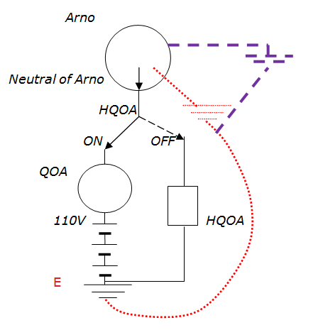
Earth Fault Relay for protection of 380V 3phase AC power circuit for Auxiliary Motors and associated circuits (QOA): Auxiliary Motors are three phase induction motor provided for cooling of power handling equipment such as transformer, rectifier, smoothing reactor, traction motor etc., compressor, oil pump of transformer etc. Three phase power is generated from single phase by rotating equipment called ARNO in conventional locos which is now being replaced by Static Inverter. Locos with SIV, are also provided with QOA and also with its own internal earth fault monitoring. Functioning is similar to QOP is shown in the diagram. It has been observed that when there is a fault inside a motor, tripping through QOA is invariably along with smoke emission.
It is important to note that QLM, QRSI, QOP, QOA, Q44 are important protection relays with normally closed interlock provided in MTDJ (DJ maintaining coil) branch and causes immediately tripling of the locomotive.
QE
The relay detects over current through auxiliary transformer for braking excitation. Current Transformer ELM detects of 1000/5A rating e over current if more than 900A trips braking excitation contactor C145.
QF
The relay detects over current through braking resistor by sensing voltage drop across shunt . There are many other relays for other system and specific protection
Slipping Device Differential Relay QD 1-2 Wheel slip relays of current differential type are provided. When the current difference is 125 A in between motors 2 and 3 and motors 4 and 5, the relay operate. In case of slipping, it feeds relay Q-48, thereby energizing sanding electro valves, VESA and sand is applied to corresponding wheels. Relay Q-51 is also energized causing regression of tap changer till the slipping stops.
Traction Motor Relay Q-20 Relay Q-20 which is connected via resistance RQ-20 across rectifier output causes buzzer SON 1-2 to work, if voltage exceeds 854 V. When voltage falls to 740 V, buzzer stops working. No Voltage Relay Q-30 The relay Q-30 drops out if the single phase auxiliary winding voltage drops below 215 volts. Its contacts switch off relay Q-44, thereby tripping DJ.
Relay Q-30 is switched on directly via the contacts of the relay Q-45 and is fed via resistor RQ-30 after the relay Q-45 opens/drops. In practice, this relay has never been found detecting low voltage but functions only as a no volt relay.
ARNO Starting Relay QCVAR Relay QCVAR has been put across ‘W’ phase and neutral of ARNO to ensure proper starting. This cuts out ARNO starting contactor C118. It picks up at 155-160 volt a.c. Battery Charger Signaling Relay QV-61 This relay, which has been provided across the battery charger CHBA, indicates the working of the charger. This relay operates at a voltage of 68-136V d.c.
Regression Relay QRS Relay QRS is energized when the loco is in running condition and de-energized when the brake is applied. This relay operates Q 51 relay through its N/C contacts and regress the tap changer.
Passenger Alarm Relay (PAR) This relay operates in case of Alarm chain pulling or train parting. The relays will energies the buzzer B1 & B2 and extinguish lamps LPAR 1 & LPAR 2. This relay has specific importance to alert the loco pilot of the train coming from other direction automatically in case of derailment and uncoupling of hose pipe. There is every possibility of infringing other line causing collision. Functioning of this relay cannot be compromised in any situation.
110V DC Power Supply for control system.
110V DC power supply for control system is floating which provides redundancy of protection. It means that if there is one fault, it will not cause any problem in working of the locomotive.
You may also like:
- ‘EARTHING’, a must for every one to understand its importance…
- Indian Electricity Rules, 2005 defines the basic fundamentals of Electricity…
- Understanding electical cable and and its role in fire
- Electrical Protection System -Train Lighting and Air Condtioning
- How to be confident about safe use of electricity?
- Electrical accidents waiting to happen…


I want Reactors what is the purpose of smoothing reactors