Study material for SSE/JE examination by RRB on Electrical Engineering Part II
There was a hostile war between AC and DC at the end of 19th century between The Edison Company, the original company holding patent for DC system and The Westinghouse Company using patents filed by Tesla for AC system. The war was similar to what existed in 21st century between Apple and Microsoft. Finally, the entire 20th and now 21st century belongs to AC system. In fact, there existed AC vs DC war in the selection process of traction voltage, and if interested, read more on the eternal war between AC and DC
The entire scenario of electric power generation, transmission, distribution and utilization is on AC system with few exceptions. DC utilization is limited to low power devices (solid state electronics), Battery Storage and devices working on it, 750/1500 V DC Electric Traction for metro transport, HVDC transmission etc.
However, understanding AC is important for all aspects of electrical engineering
Waveform
There is a circular motion during which power is induced. The magnitude of induction various continuously during the cycle resulting sinusoidal waveform. The sinusoidal waveform results varying magnetic field around it, making the transformation of voltage simple and wide range of application. Power generation, conversion, transmission, distribution and utilisation is simple when it is AC. Voltage and current are written as v=VPeakSinϕ and i=IPeakSinϕ. Φ is a function of time and frequency, and written as ωt or 2πft. The varying nature of power supply with positive and negative cycle brings some interesting behaviors which are not there with DC. The factors such as Period (T), Frequency (f), Instantaneous Value (v,i), Peak Value (V,I), Peak to Peak value (2V, 2I), Root mean square and Average value are important one should understand of a periodical waveform.
Period: Time take to complete a cycle is called Period and denoted by T, unit as sec or s, and as shown in the diagram.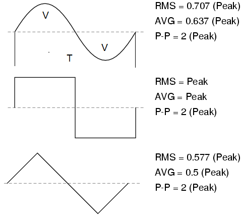
Frequency: No of cycles per second is frequency and also calculated as f=1/T.
Instantaneous Value: It is the value at any instant on the cycle, denoted by small v or i and written as v=VSin(2πft);
Peak to Peak Value: As it suggests, it is generally twice the peak voltage/current when it is same in both part of the cycle.
Root mean square (RMS): As the instantaneous value varies continuously, the RMS value is to understand the work output. Its value is Vrms=V/√2. √2 is called the crest factor. For 230V rms voltage system, the VPeak is 230√2=325V. The crest factor is √3 and 1 for triangular and square waveform.
Average value: Average value is an indicator of the total charge flow in a complete cycle. Vavg=2VPeak/π, or it is Vavg = 0.637VPeak
Form Factor: It is the ratio of RMS value and Average value i.e. Vrms/Vavg. For sinusoidal waveform the form factor is π/2√2 which is equal to 1.11. It is said that this is one of the reason for defining standards of voltage as multiple of 1.1, beside other reasons of the factor of 4.44 in the induced voltage etc.
Behavour of AC circuits
AC power supply circuits behave differently as compared to DC power supply and its circuits. The voltage and current moves in phase in DC circuits whereas in AC it is either lagging or leading. This is because of the action arising due to the electro-static and electro-magnetic effect 0f the static and moving charge (electron) and its reaction. This makes the study very interesting, study of systems through mathematical modelling, derivation and integration, and difficult also. Step by step study simplifies the complications involved in it.
Purely electrical resistive circuits behaves similar to what is there in DC system but magnetism get involved when studying AC system.
Understanding Magnetic Circuits
Magnetic circuits is having similarly with resistive circuit following Ohm’s law and makes the understanding easy. A table below compares the two class of circuits and its similarities. 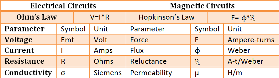
Inductor
Inductance is the property that opposes any change. This opposition is due to inducement of opposing reaction. When voltage applied to an inductor with amplitude changing with time, the current does not change simultaneously but with a delay. There are three laws which describes the theory behind this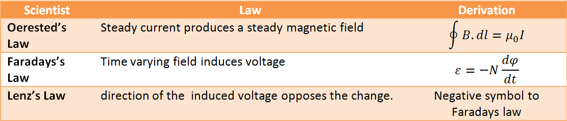
The symbol of inductance is L in the honour of Lenz and unit Henry in the honour of Joseph Henry. Henry discovered electromagnetic induction independently and at the same time of Faraday. He also described that the inductance is one henry, if current varying at the rate of one ampere per second will induce one volt in the inductor. Inductor consists of number of turn, Length and Area of the core and permeability of the magnetic material and derives as follows:
Similar to electro-motive force (emf or voltage) we have magneto-motive force (mmf) equal to No. of turns x current flowing through it i.e. N*I and unit A-t. This magento-motive force produces magnetic field intensity H equal to A-t/meter or N*I/ l (where l is path length in meters). This magnetic field intensity produces flux φ (in webers) equal to B*A. Flux linkage with the coil is given by N φ and inductance by flux linkage per unit current i.e. L=N φ/I
Now substituting the value of φ=BA, B=μH, and H= N*I/ l, we get L=(μ*N2*A)/l
Therefore, Inductance is proportional to the square of the number of turns and area of the core but inversely propotional to the length of the core. It only says that the more closely packed turns will give more inductance.
Application of Inductor
Inductors along with capacitors are used in electrical system to contain, maneuver and tame the behavior of alternating voltage and current. There is one strong limitation of using inductor is of size in reference to both weight and volume and therefore, capacitor is preferred unless unavoidable.
Filters: Inductors are used as in filters along with capacitors and resistors. The impedance of capacitor decreases whereas that of inductor increases with increasing frequency. The combination can be design to pass or block one particularly range of frequency.
Sensors: Inductors can provide contact less sensor for sensing magnetic field and ferro-magnetic materials.
Energy Storage: Energy stored in a inductor is ½LI2 but it stored only when the circuit is active and discharges immediately when source is removed. However, this is used in switched mode power supply.
Choke: Chokes were used widely along with a starter for producing high voltage to ignite the discharge tube for illumination by florescence effect. Due to energy loss, now the chokes have been replaced by electronic choke.
Transformer and Motor: These two items are independent equipment but works on the principle of induction and will be discussed separately.
You may also like:
- Why Faraday’s research is revolutionary to start the era of…
- Indian Railway Context – Sanding to improve adhesion
- Why IR passenger traffic heading south?
- Where to begin to understand Electrical Engineering?
- Study material for SSE/JE examination by RRB on Electrical Engineering…
- How Resistance is important in understanding Electricity?
hello;sir this is pavan i wnt to know about the complete details about rrb je/sse give me some sujjestion and reference books names or pdfs to my mail,thank you.
Visit the website and you will find answer to all your quarries of job profile, RRB examination, previous year papers and sample papers, syllabus etc.
Is there any electronics subject material for railways available ????? Or suggest me agood book for basic study of electronics electrical computer subject for railway sse je??
There can not be a good book specifically for SSE/JE for RRB jobs. The syllabus is very clear and whatever you have studied in your Engineering during the first two years shall be sufficient. No examination is held exclusively for electronics/electrical/computer but all branches together. Hence, you have to prepare for all the branches of Engineering. If you go through the trend of examination in the past, sample paper attached, you will find and can make up your mind, what you have prepare.