Weight Transfer
Issue of weight transfer is of significance while demanding high tractive effort generally on gradient, and gradient will also add to unloading of leading axles. There are basically three contributory factors
Body reaction
- Height of draw-bar and centre-pivot.
- Distance between loading points on front and rear bogie
- Secondary suspension
Bogie reaction
- Direction of noses.
- Height of centre-pivot.
- Primary suspension.
- Diameter of wheel.
- Nose Reaction
- Distance between TM nose and axle centre.
- Direction of noses.
Weight transfer due to force exerted by Traction Motor: Whatever force is exerted by the traction motor at pinion teeth produces reaction force at support as per Newtons third law of motion. In case of axle hung and nose suspended arrangement of traction motor mounting, the reaction forces will appear on axle and nose are as shown below in the diagram: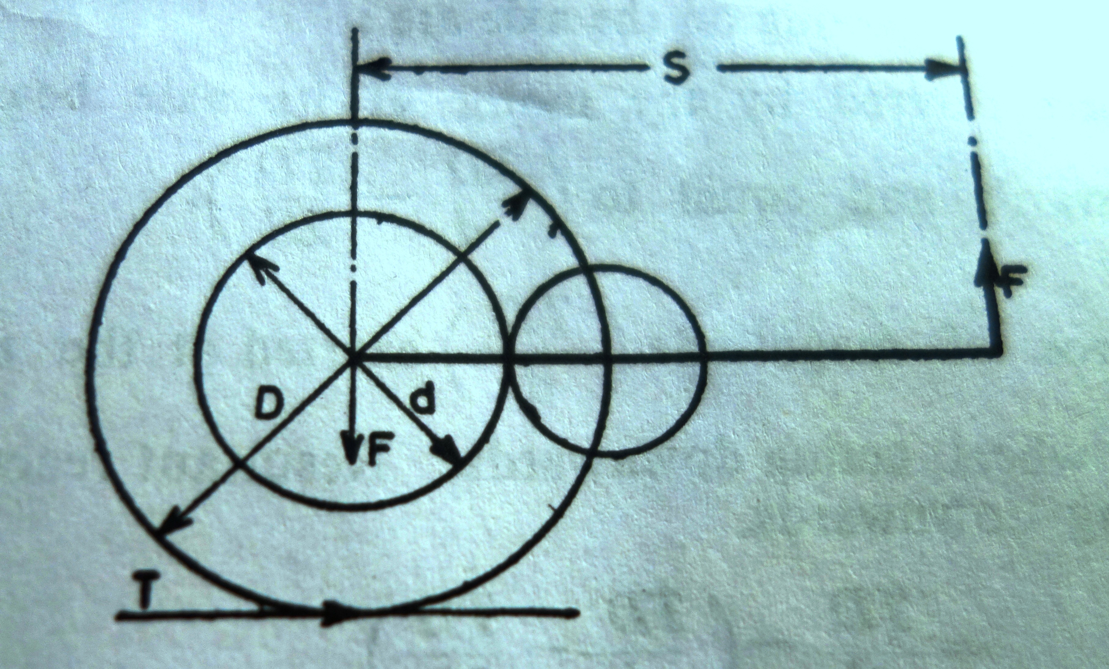 The force FT is calculated as TD/d and its direction is downward for left to right movement. Now, FNxS = (TD/d) x (d/2) or FN = TD/2S upward and FS = (-) FN

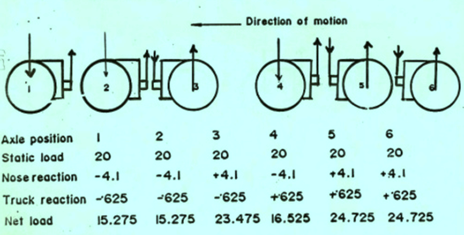
Effect of nose versus direction of motion
Axle mounted motors when exerting TE causes a reaction force at the motor nose and equal and opposite force at the motor suspension bearing. When the vehicle is moving in the direction of nose, the axle bearing presses downward on the axle. These forces are reversed when the vehicle is moving in other direction. This in actual scenario of WAM4/G5 class of locomotive is calculated as follows: Loco wheel diameter is 1092mm, distance between pinion to nose is 800mm and if the applied TE is 6 T, then reaction force on the axle is calculated as (1092×6/2×800)=4.1T and its affect on the axle weight make a significant variation as can be seen from the diagram above.
Weight transfers due to drawbar pull: Tractive effort developed at the tread of the wheel is transferred from the axle to the bogie frame through drag link/horn cheek and from bogie frame to locomotive body through low traction bar/centre pivot and finally to drawbar. The height difference of centre pivot and that of drawbar pull results in a couple acting on the body of the locomotive. This causes weight addition on the trailing bogie and equal reduction on the leading bogie. Again due to the transmission of tractive effort from bogie to body of the locomotive, the bogie is acted upon by a couple with similar affect.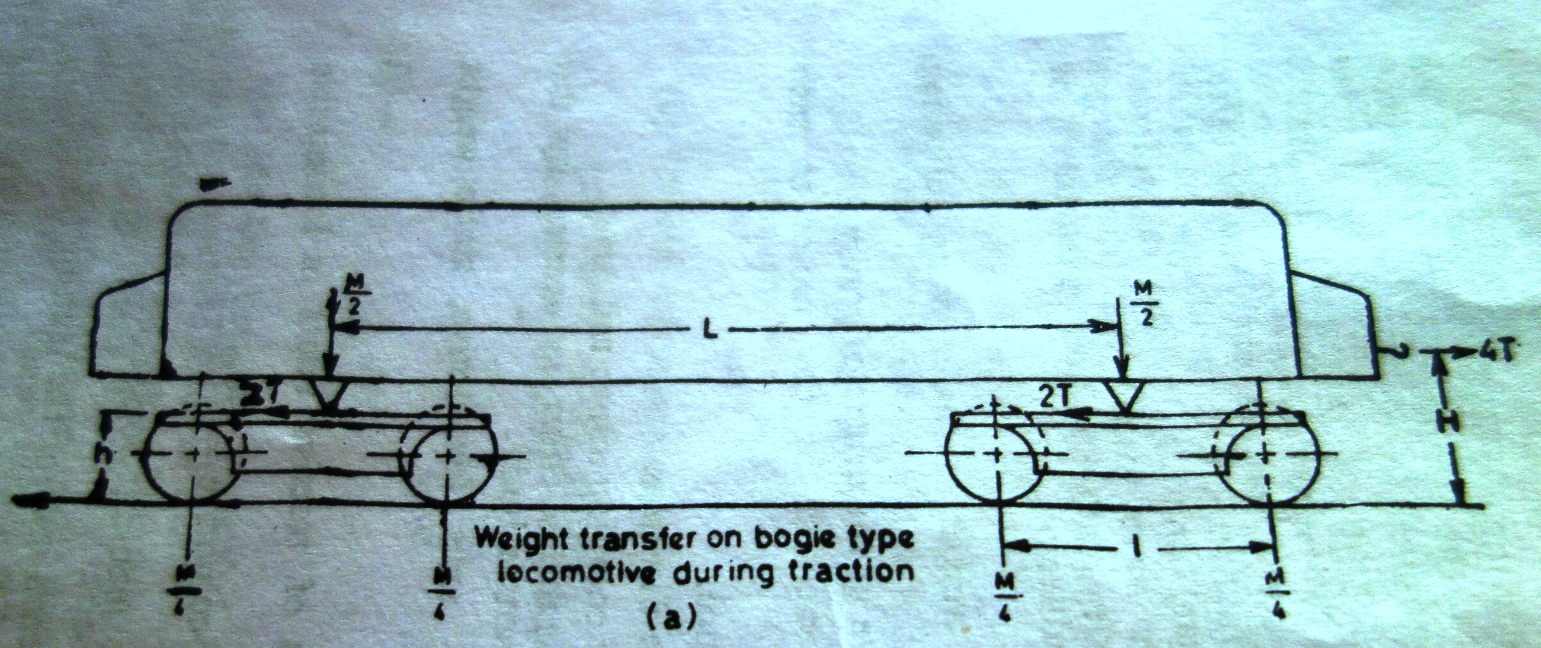 Now assuming that mass of locomotive is M, Tractive effort as T, bogie centre distance as L, bogie wheel centre distance l , height of drawbar coupling above rail level is H and height at which tractive effort is exerted by the bogie on the locomotive body is h, then on a 4 axle locomotive
- Static weight on each axle is M/4
- Couple acting on the body of the locomotive is 4T(H-h) and reduction of weight on leading bogie is 4T(H-h)/L
- Couple acting on the bogie of is 2Th and its effect of reduction of weight on the leading axle is 2Th/ l. Final weight distribution due to weight transfer between bogie and between axles of the bogies is as given in the table.

Formula for weight transfer due to body
Net weight transfer of WAM4 class of locomotive
Effect of M, L, H and l on weight transfer: Now here M is fixed by the maximum axle load limitations, L is fixed by the overall length of the vehicle and H is fixed by the standard of vehicle. However l is adjustable to limited extent in view of the safety consideration arising due to negotiation curves, points and crossings etc. This can be varied in case of fully suspended motor to some extent but limited in case of axle hung-nose suspended motor by diameter of the wheel and size of the motor. Effect of h: Reducing h will have desirable effect on the weight transfer between the two axles of the bogie. Reducing h will increase the factor 2T (H-h)/L whereas will reduce the factor 2Th/ l . Weight transfer between the axles of the bogie of conventional design is of the order of 15-20% of the adhesive weight of the locomotive and between the bogies is 1-3% therefore net results is favourable to minimise the total effect. Reducing h thus becomes an important feature in the design of any traction vehicle. The designed followed to reduce the weight transfer had been vertical coupling between bogies, double tilting pivots, low traction bars etc. low traction bar design had been followed in WAM1 and WAG1,4 class of locomotive which were imported from Japan and SNCF. Subsequently, IR followed WDM2 design locomotive in WAM4 and WAG5 design where the weight transfer between bogies and axle is very high. Designs followed in new series of locomotive, the weight transfer reduced considerably by following WAG6C/WAG7, WAG9 and WDG4 etc. WAG7 is an indigenous version but with bogie designed as followed in WAG6C locomotive imported from Hitachi Japan. The important differences are
- Traction motors are axle hung and nose suspended in both the bogies. But WAG-7 bogie has unidirectional noses as compared to two forward and one reverse combination (and vice-versa on second bogie) of WAM-4.
- Primary suspension of WAG-7 consists of sets of equalisers hung directly on end-axles boxes and supported on middle axle-box through a link and compensating beam arrangement. This special mechanism re-distributes the loads equally on all the three axles. Unlike this, WAM-4 has two sets of equaliser beams – one each between either end axle and supported at middle axle but not connected to each other. Hence differential loading of front and rear springs can cause unequal loading of axles.
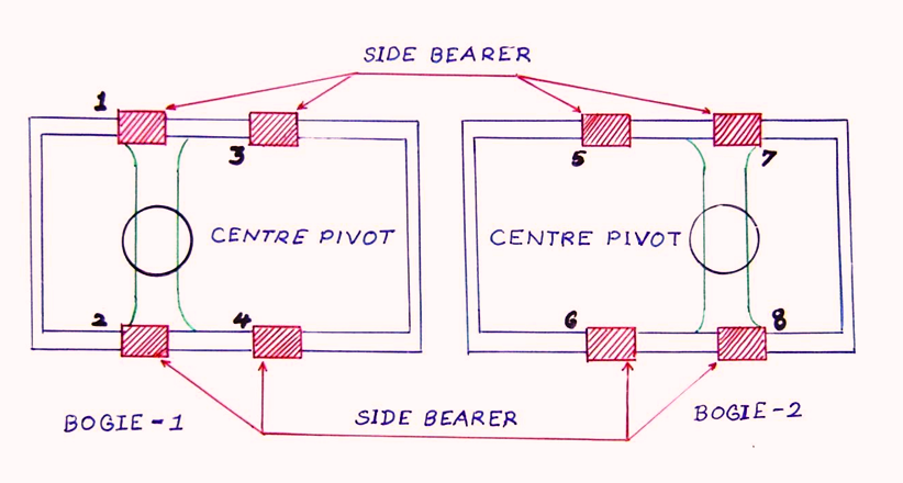
- WAG-7 is provided with a low centre-pivot that does not carry any load. Secondary suspension comprising of stiff steel rubber pads and transfer the tractive effort from the bogie to body. WAM-4 has centre-pivot and side bearer at a higher level in a tri-mount arrangement.
Comparing design features of different bogies followed in Mixed and freight locos over Indian Railways
The design of bogies plays an important role in transferring the weight of locomotive to the rail and adhesive weight to load through the body. It has to absorb all types of vibrations with provision flexible links between sub-assemblies. There are three basic design followed on freight locomotives presently in service namely WAM4/WAG5, WAG7/WAG6C and WAG9/WAG9h. The important features with photographs are narrated below.
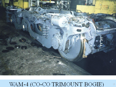
WAM4/WAG5
- Casted tri-mount bogie with three point support one at centre and two side bearers. Centre pivot provided at the cross member.
- Centre Pivot caries 60% of the load and transmit tractive and braking effort from bogie to body.
- Side bearer carries 40% of the load but does not transmit tractive or braking effort
- Four groups of helical coil springs on primary suspension and four snubbers
- No secondary suspension
- Equalisation by suitable positioning of springs and control of working height
- Wheel base is 3810mm with un-equal distance between two wheels of 1702mm and 2108mm


 WAG6C, WAG7 & WCAM3
- It is a fabricated bogie with full support by rubber sandwich side bearer. 60% by side bearer close to centre pivot and 40% by balance side bearers. Centre pivot is floating does not take any vertical load but helps in transferring tractive and braking effort.
- Equalising beam provided to reduce effect of weight transfer from wheel to bogie.
- The design provides uni-directional mounting of traction motor.
- There is primary suspension of helical springs between bogie and wheel whereas, sandwich rubber mounting between body and bogie for load transfer and secondary suspension. Lateral and vertical oil dampers are provided for damping the oscillations.
- Wheel base of 3800mm of equal distance between two wheels of 1900mm each.

 WAG9 and WAP7
- It is a fabricated bogie and body weight is supported through helical springs, 4 nos. per each bogie.
- There is no centre pivot and tractive effort from the bogie to body is transferred through low traction bar. The height of effort transfer (h) reduced considerable resulting very low impact of weight transfer due to body. Vulkollan rubber ring is used in the housing to absorb the shock of tractive effort transfer.
- Cylindrical roller axle bearing with wing type axle boxes (SGCI) is used with primary helical spring on the wings. Wheel set guidance is flexible.
- Axle hung nose suspended motors with all nose in one direction


 Based on the above designs, the weight transfer efficiency has been worked out and found to be of the order of WAM4/WAG5 – 80%, WAG9/P7 – 93%, WAG7 – 94% and WAG6C – 97.4%. The axle weight of WAM4/WAG5 is 19.8T and weight transfer during maximum transfer of tractive effort is (-)2.4, (-)2.6, (+)3.7, (-)3.7, (+)2.6, (+)2.4 whereas the weight transfer in WAG7 with axle weight of 20.5T is (-)1.34T on each axle of leading bogie and (+)1.34T on each axle of trailing bogie.
Algorithm for calculation of Weight Transfer
- State all dimensions of the assembled bogie with reference to vertical and horizontal distances.
- Calcualte nose reaction as stated above
- Calculate body reaction as stated above
- The unknowns are changes in respective spring pressures ( ∆Fi). Now develop simultaneous equations as under :
- Balance of forces at the bogie frame : The forces due to change in spring pressure, nose reactions acting on the bogie frame and force due to body reaction acting through secondary suspension shall add up to zero.
- Balance of moments of forces acting on the bogie frame around a suitable pivot (Generally a point in the top of bogie frame in line with the centre line of middle axle is appropriate) should be zero.
- Geometric condition of rigid bogie frame or rigid under-frame of locomotive may be applied to establish a relationship among spring pressures.
- Properties of springs. Usually springs used at different locations may be identical. In such cases, the deflection of spring will be a proxy for the force.
By solving these three equations, the change in loading of springs due to dynamic loads can be determined. 5. Next step is to distribute the spring loads across axles if the springs are not directly mounted on axle-boxes. The load should be distributed proportionately among the axles with the one closer to the spring sharing more. 6. Calculate the net effect on each axle by algebraically adding the force due to spring load and one due to nose reaction.
You may also like:
- Weight Transfer during Braking
- Selection of Suspension Arrangement of Traction Motors : A Right…
- What is Electricity, Drift Velocity and Electric Current?
- Re-engineering of Stators of Three phase Traction Motors type 6FRA…
- How a locomotive works a train?
- Multiple Choice Question on Basic Concept of Science Class X…
Hello Sir,
I have gone through the weight transfer in the locomotive axles paper published by you in railelectrica. I was very informative for me since i am also working on a locomotive project now. Basically i am a mechanical engineer and Sir i would like to know more about the weight distribution on the CO-CO bogie in which 2 axles are powered having a static axle load of 21 Tons.
Can you please able to give some inputs on how the adhesion and the axle loads distributed on such bogies, that will be very helpful for me.
Why you want only two axle driven per bogie in a CO-CO arrangement. There is no such design available and hence no design calculation as well.
Thank you for your reply sir.
Actually we are on a development project to check the possibility of traction by powering 2 axles of the CO-CO bogie for a shunting locomotive using a hybrid power system with minimum power requirements. So we are finding the possibility of traction by 2S-2P configuration of the traction motors.
Can u please give your expertise advise on what will be the design challenges when using such a system and how it affects the adhesion and traction of the locomotive.
NAMASKAR. WHILE WORKING OF WAP-4 LOCOMOTIVE WITH 24 COACHES, TRACTION MOTORS NUMBERS 1, 2 & 4 ARE DRAWING LESS CURRENTS THAN THE OTHERS. PLEASE GUIDE WHY IT SO?
Can you provide me with weight transfer calculations of a diesel hydraulic locomotive.?
B-B Locomotive with inner axles driven by cardan shafts.