DC Series Motor as Traction Motor
There are two basic principles which governs the working of DC machine
- A current carrying conductor placed in a magnetic field experiences a force demonstrated by Lorentz Law. Direction of the force is given by Fleming’s LH rule.
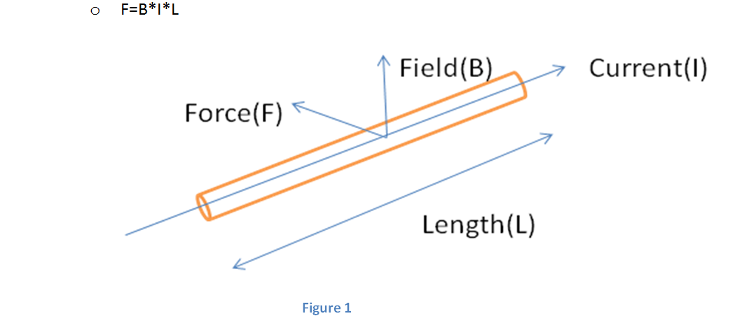
- A voltage is induced in the conductor moving in a magnetic field (Faraday’s Law). This voltage is induced so as to oppose the magnetic field.(Lenz’s Law). Let the conductor moves with a velocity of V m/sec on account of Force experienced, then
- e=BxLxV
Derived from Faradays’s law
- e=(–)Nd
/dt
These two equations derives all equations of DC Traction Motor
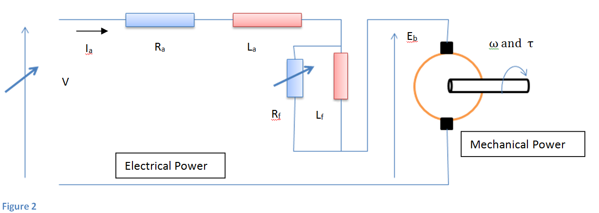
Equivalent circuit of DC Series Motor
- V=Eb+Ia(Ra+Rf); Eb=P
IaxN or N
- Speed
Speed is inversely proportional to armature current; field current is same as that of armature unless partly diverted therefore can also be said to proportional to field
- Power=Eb*Ia=Torque*angular speed= T*2πN/60
(PφZN/60A)*Ia = T *2πN/60
or T = (PZ/2π) φ*Ia
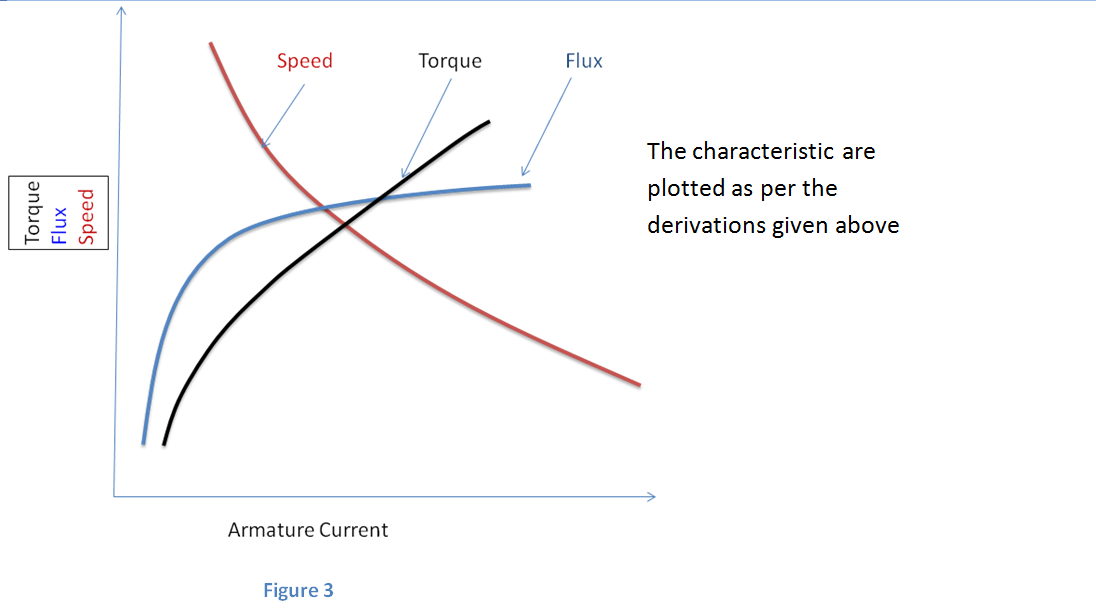
T ∝ φIa or T ∝ Ia2 (Unsaturated field)
∝ Ia (Saturated field)
Torque is directly proportional to the square of the armature current resulting high starting torque and directly proportional when field is saturated. Starting Armature current is high, and field is thus saturated early.
- By substituting value of Ia in torque equation we get
T ∝ 1/N2 : when field is unsaturated and
∝ 1/N : when field is saturated
HP ∝ Speed*√Torque : before saturation means
HP ∝ Speed * Torque : after saturation
It provides higher torque within rated HP up to saturation.
For deriving tractive effort and speed characteristics to match the load, variables are applied voltage and field flux. This achieved by varying the Single Phase 25kV AC Voltage through on load Tap changer, rectification, smoothing and applied to Traction Motor. Voltage can be varied in 32 steps. Field is varied by Resistance insertion in parallel to field though shunting contactor in 3 to 4 steps in WAG7 and WAP4 locos respectively.
Torque/flux/speed vs armature current characteristics
Deriving Tractive Effort Vs Speed characteristics
Limits are set on the torque speed characteristics of Series motor as Tmax and Smax as per the design parameter. Tmax is fixed on the basis of short term thermal rating of the motor and adhesion available where Smax depends on the mechanical design and the services the locomotive has to perform. Applied TE of tap changer locomotive is in steps due to tap changer control and peak has to be kept within adhesion limit therefore average TE applied is always less then adhesion limit.
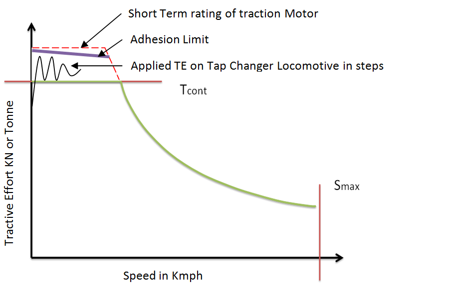 Figure 4
Speed Torque Equation of DC series motorLimits are set on the torque speed characteristics of Series motor as Tmax and Smax as per the design parameter. Tmax is fixed on the basis of short term thermal rating of the motor and adhesion available where Smax depends on the mechanical design and the services the locomotive has to perform. Applied TE of tap changer locomotive is in steps due to tap changer control and peak has to be kept within adhesion limit therefore average TE applied is always less then adhesion limit.
V= Eb + Ia (Ra +Rf); Eb =k1ΦN; T= k2ΦIa
Substituting value of Eb and T in voltage equation and solving for speed, we get
V= k1ΦN + T (Ra +Rf)/ k2Φ = k1ΦN + k3T/ Φ
N=[ V/ k1Φ – k4T/ Φ2]
When voltage and flux is kept constant, this equation is of the form,
N=A-BT where A determines the intersection on speed axis and B is slope of the curve

Working Principle of DC Motor
The field is stationary and generated through main poles on stator frame. The armature winding is a closed winding through the Commutator and current is supplied through the brushes. Brushes are placed along the neutral axis of stator field. The mmf produced by the field (Ff) along the magnetic axis while the current flowing through the armature produces an mmf (Fa) directed along the brush axis. The two mmfs are in space quadrature and occur simultaneously in the motor. They react with each other and develop a torque under whose action the armature rotates. A voltage induced in armature can be determined by the Fleming’s left-hand rule. The picture below demonstrates field and its interaction to produce torque.
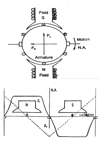
mmf diagram of DC Motor
You may also like:
- Selection of Suspension Arrangement of Traction Motors : A Right…
- Multiple Choice Question on Basic Concept of Science Class X…
- What is Electricity, Drift Velocity and Electric Current?
- Re-engineering of Stators of Three phase Traction Motors type 6FRA…
- Selection of Suspension Arrangement of Traction Motors : A Right…
- Current Developments in the field of Traction motors
Nice
Very nice and helpful explanation