2×25 kV Traction System
What is 2×25 kV traction system
2×25 kV traction system means transmission at 50 kV and using at 25 kV voltage system. 50 kV transmission benefits for
- Improved voltage regulation and reduced transmission line losses
- Increased Traction Substation spacing
- Improved Load factor as number of trains fed per feeding post are more
25 kV traction voltage system benefits for
- Seamless running of locomotive from 1×25 kV to 2×25 kV traction system
- Feed extension from one system to another possible
but at the increased cost for
- Additional feeder wire
- Provision of Auto-transformer at each SP and SSP
Therefore, deciding to go for 2×25 kV traction system shall be a result of simulation studies based on load, voltage drop etc. and of following factors:
- Is it compatible with the service level today and in future and commercially viable? The financial benefit accrued by saving on energy and voltage regulations vis-a-vis additional cost. It is not so easy to have 1×25 kV today with a provision to change over to 2×25 kV at a later stage. When we are sure that traffic density will certainly go up, system shall be designed to cater that need.
- Is mitigation of electro-magnetic induction is necessary requiring provision of return conductor and booster transformer? If yes, it will add to financial benefit.
- Is it proven and technically viable? How it benefits the local industry and in-house development of technologies for the future or depends on import?
- Is it compatible with infrastructure? How costly the real estate is in the vicinity of Rail network? 2x25kV will find more application in Metro cities by reducing number of Traction sub-stations.
Limitations of 1×25 kV traction system
1×25 kV traction system normally called as 25 kV traction system was initially provided with 2×12.5 MVA traction transformer and inter substation distance of 50-60 Km. Electric Traction has the distinct characteristics of attracting traffic by B routes and thus very slowly traction system starts getting overloaded. Transformers have been upgraded to 21.6 MVA and many a placed additional sub-stations were added to the system to address the issue of voltage regulation. This added neutral section in the system calling additional duty of switching off and on of Circuit breaker while passing these neutral section. Even though precautions of for-warning the loco pilot at 500M and 250M is taken, but there is even one in millionth probability of its missing, it may then result into flash-over while passing from live to dead zone. One of the steps taken to take care of voltage drop was to remove the booster transformer after careful studies and thus removing unnecessary elements of additional impedance. Now there is a serious thought to look for ways to convert 1x25kV traction system into the 2x25kV traction system. The main problem for this is to run a return conductor on the existing mast, which is a very difficult proposition requiring long period blocks, which is almost impossible looking at the existing level of traffic. It will thus require running the return conductor on separate mast, of course a costly proposition.
This is now a subject of innovation, technology advancement in execution of work etc.
How 2×25 kV traction system works?
The system of 2×25 kV is based on distributing power at 50 kV and feeding to the vehicle at 25 kV. For this the Traction sub-station is provided with a center tap secondary winding at 50 kV (55 kV for the maximum limit of contact wire voltage of 27.5 kV). Center tap is solidly connected to ground thus one terminal is at +25 kV and another at -25 kV or we may that the two supplies at a phase difference of 1800. Traction line is fed by +25 kV and a feeder wire at -25 kV thus the voltage in between these circuits is 50 kV but to ground is 25 kV. Therefore, the insulation or clearance is designed for 25 kV only.

Showing Catenary and Feeder wire

2×25 kV Traction Transformer

Solidly earthing of Mid point

Auto Transformer at Sub-sectioning and Paralleling Post
The system 2×25 kV shall always end at auto transformer center, therefore at each side of the neutral section between two sub-station, an auto-transformer center must be located. The rest of the auto transformer center will be located along the line at SSP. In fact, auto transformer of 54/27 kV voltage rating is located at every 10/15 Km of which outer terminals are connected between the catenary and the feeder wire.
Current distribution in an Auto Transformer
Let V1 and V2 are the terminal voltages of the primary and secondary windings of auto transformers with a turn ratio of n1 and n2 respectively and the induced emf are e1 and e2 with a current of i1 and i2. Then
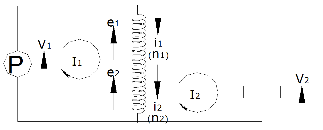
But i1 = I1 and i2 = I1-I2 and also n1 = n2, then we get i1 = I1 and i2 = I1 hence current in the series winding is equal and opposite to common winding and therefore no current flows through mid point or rail in the section.
Actual current distribution in 2×25 kV traction system


Actual layout of TSS with Scott connection transformer
Please provide the connection diagram(terminal connections) of Auto transformer used in 2*25kV traction system. And if possible please provide the overall current flow diagram from Grid transform the through feeders and the the ending auto transformer.
Sir, what is impedance of 2X25 kV OHE.
Images & notes
Good knolge for job perpath essay concept
Is separate auto transformer center is requisite inspite of having Auto transformer at SP’s , SSP’s & TSS .please advice.