Wheel Sets
A wheel set consists of two wheels rigidly connected by a common axle and provides
- Necessary distance between track and vehicle to support equipment mounted on under-frame
- Guidance for motion to contain within track gauze
- Transfer of vertical load to the rail
- Transfer of tractive and braking effort to rail
It’s design depends upon
- Type of vehicle i.e. traction or rolling
- Types of bearing to support vehicle and traction motor
- Type of braking system i.e. shoe or disc
- Use of resilient bearing to restrict the transfer of high frequency vibration to the vehicle
- Selection of wheel profiles as per track profile and norms of riding index at a specific speed potential
- Un-sprung mass on the wheel responsible for generating high frequency vibration. Need for resilient wheel to reduce wheel-rail interaction forces
Wheel Profile
- To keep the wheel on the rail and inside the gauze taking care of the varying slackness of the rail gauze
- To permit different angular velocity of two wheels on the same axle at curves
- On curves the distance travelled by the outer wheel is more than the inner wheel. This requires higher angular velocity for the outer rail and conical design of profile makes this possible. Otherwise, the inner wheel will slip on the support of flange causing excessive wear
Important Dimensions of Wheel Profile
- Flange: Guides the wheel with height 28-30mm
- Flange Inclination angle 65-70°
- Root
- Tread: Rolling is on tread
- Chamfer: Relief at outside to ease the motion at switches
- Wheel gauze:
- Conicity: 1:10 to 1:20 at tap angle which goes to 1:40 for high speed to prevent hunting
- Width of wheel: 125-135 mm
Factors responsible for Wheel wear
- Curvature
- Suspension Design
- Level of Traction and Braking forces
- Average Rail structure (rail, sleeper density and cushion) encountered
- Lubrication particularly on curves
Effect of Wheel wear
- Cost
- The cost of a wheel disc/loco (12 in numbers) is Rs. during 2012 and constitute a significant cost towards maintenance.
- Cost of restoration of profile on under-floor wheel lathe
- Safety
- Tread wear will increase the height of the flange which may hit the fish plate or other fittings at switches
- Excessive concave at tread will develop false flange causing damaging stresses
- Flange wear will lead to increase in flange angle and reduction of the flange thickness and possible splitting of switch
Wheel Set Life
- On traction wheels, the tread wear is very slow as compared to flange and root wear. This is the primary cause of locomotive taken for wheel turning. For this reason, service limit of wheel diameter can be made use for the purpose of delaying wheel turning.
- Tread wear is more pronounced on freight locomotive as compared to passenger locomotive due to demand of higher tractive effort.
- Wheel Flange lubricators were tried on sample locomotive to reduce flange wear but not successful due to design and maintenance issues. Manual lubrication of rail gauze is being done but only on sharp curvatures. Lubrication has direct impact on improving wheel life, reducing noise etc.
Permissible difference in Wheel diameters
| WAM4 | WAP4 | WAG9 | WAP5 | WAG7 | ||||||
| New | Service | New | Service | New | Service | New | Service | New | Service | |
| On the same Axle | 0.5 | 2.5 | 0.5 | 1.5 | 0.5 | 2.5 | 0.5 | 2.5 | 0.5 | 2.5 |
| Same bogie | 2.0 | 8.0 | 2.0 | 5.0 | 2.0 | 4.0 | 2.0 | 4.0 | 2.0 | 8.0 |
| Same Loco | 15.0 | 25.0 | 15.0 | 20.0 | 15.0 | 20.0 | 15.0 | 20.0 | 15.0 | 25.0 |
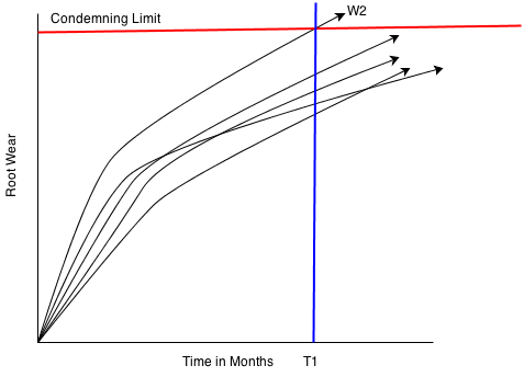
The wear on the six wheels is always non-uniform. There may be one wheel wearing faster as shown above wherein W2 is wearing faster as compared to other wheels. If wheel turning of all the wheel is taken up due to one such wheel, then loss of material on other wheels will be unnecessary thus affecting wheel life. Below is shown the general trend of root wear vs month of working.
Following alternates to handle such situations
Change one wheel if only one wheel is worn out and wear on other wheels is significantly less. Time taken for changing one wheel set is almost same as for turning the wheels.
Turn only one bogie making use of the permissible wheel diameter difference between two bogies
Wheel life is generally calculated by dividingy consumption of the wheel disc by the holding during the year. It is difficult to calculate the trend of change in feel life with the action plan put in place. Therefore, a term Project wheel Life is coined which will give a fare trend on wheel life month to month.
Projected Wheel Life =
Monitoring this figure month by month is certainly a motivating indices helping understanding wheel wear behavior and immediate reaction towards any change in the trend.