Three Phase Induction Motor as Traction Motor
Right from the introduction of electric traction, there was a strong desire to use Three phases Induction Motor for Traction application. This could only be possible with the introduction of variable voltage variable frequency control.
Working Principle of Three Phase Induction Motor
AC induction motor is equivalent to Transformer where secondary is short circuited and free to rotate. Three phase primary winding is mounted on Stator distributed spatially at 120 degree. Resultant Field flux produced in the air gap, due to time and space varying each phase flux, is of constant magnitude but rotating at a synchronous speed of Ns. The value of Ns is given by 120(f/P ) where f is frequency and P is number of poles. This flux induces emf and current in the rotor and causes it to rotate in the direction of stator flux and tries to catch it up. The induction of voltage and current in the rotor circuit will depend upon the relative motion between field and rotor. The induced emf, rotor reactance and frequency is having value of sE, sX and sf where s is called slip frequency given by (Ns-Nr)*100/Ns
Equivalent Circuit of Induction Motor
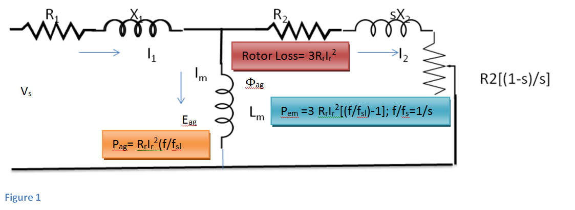
Equivalent circuit is same as that of transformer except that all values in the secondary side is at slip frequency because of induction of voltage and current in the rotor will be based on the relative motion of synchronous speed and rotor speed.
1. Air gap Flux is produced by the magnetising current Im flowing through inductive winding of the stator Lm and Φag = (Lm Im)/Ns
- From Faraday’s Law we know that; eag=Ns(d Φag/dt)
Air gap flux at any instant is given by Φag(t)= Φagsinωt
From this we get eag=NsΦagωcosωt or NsΦag(2πf)cosωt
Rms value ∝Φagf means proportional to air gap flux and frequency
Ratio of applied voltage and frequency shall be maintained constant for air gap flux to be constant.
2. Air gap flux produced is rotating at a synchronous speed of ωs and induces voltage in the rotor circuit. The frequency of induced voltage depends on the relative motion between synchronous speed and the rotor speed at any instant of time. It will be f at locked rotor and will keep on reducing to very low value with increase in speed.
Slip s(per unit)=(ωs-ωr)/ωs
Slip Speed( ωsl) sωs
Slip frequency(fsl) sf∝ sωs
Rotor Voltage Er ∝fslΦag=RrIr +j2πfslLrIr
Power crossing the airgap EagIr
Rotor Power Loss 3RrIr2
Now multiplying rotor voltage equation by f/fsl then we get
Eag = (f/fsl ) Er =RrIr(f/fsl ) +j2πfslLrIr(f/fsl)
Multiplying with Ir
Pag = EagIr= RrIr2(f/fsl ) +j2πfLrIr2 = (Active power per phase+ Reactive Power per phase)
Total active power 3Pag=3 RrIr2(f/fsl )
Electromagnetic power of rotor = Air gap power – rotor losses
Pem=3 RrIr2(f/fsl )- 3RrIr2 = 3 RrIr2[(f/fsl)-1] where f/fsl = 1/s
Tem=Pem/ωr; ωr=ωs(1-s)
Pag/Pem={3 RrIr2(f/fsl)]/ 3 RrIr2[(f/fsl)-1]= (f/fsl)/ [(f/fsl)-1]=1/(1-s)=ωs/ωr
Tem=3( Rr/ωr)Ir2[(f/fsl)-1] =3[ Rr/ ωs(1-s)]Ir2[(1-s)/s]=3(1/ωs) Ir2 (Rr/s)
Ir=sEag/Zr= sEag/√Rr2+s2Xr2;
Tem=[3(1/ωs)( Eag2)( Rr/s)]/[( Rr/s)2+X2]
Now there are two options
- When s is low-Rs/s is low as compared to X, then Tem= [3(1/ωs)( Eag2)( s/Rr)]; Tem∝s
- When s is high-Rs/s is low as compared to X, then Tem=[3(1/ωs)( Eag2)( Rr/X2)](1/s); Tem∝1/s
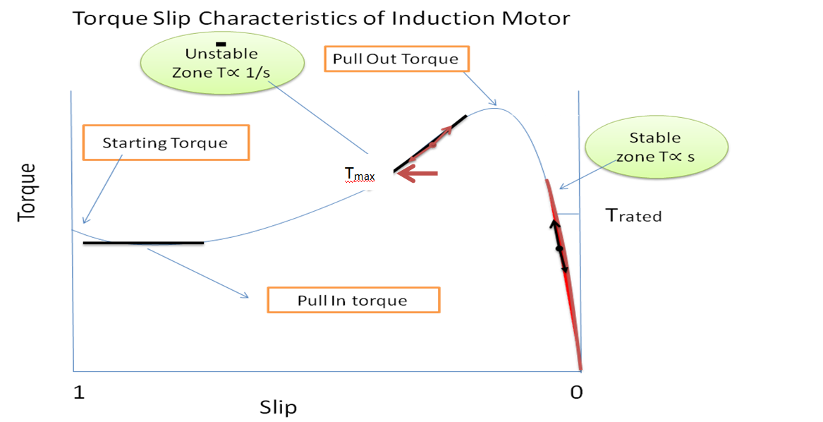
Figure 2
Stability of the torque from zero slip to pull out can be confirmed like that if there is sudden demand of torque, speed reduces and if load speed increases, torque demand reduces. This is not so in zone of pull out torque to pull in torque where if speed increases demand of load also increases. Induction motors are preferred to work much below pull out torque as shown Trated to deliver full power at rated speed. Tmax is short time torque to utilize short term thermal rating of the motor.
Speed Control of Traction Motor
Speed of an Induction motor depends only on number of poles and frequency of applied power supply from the formula ωs=120f/p or to some extent by reducing the supplied voltage which results in reduction of generated torque resulting in reduction of speed. These speed control method could not find any universal application for any purposeful gain. There is one example of using pole change from 4 to six pole for twin speed vacuum exhauster used on WAG1 class of locomotive for quick creation of vacuum after application of brakes.
With the development of advance power devices like thyrister, GTO and IGBT, frequency control became feasible.
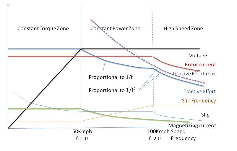
Speed-torque characteristics of Induction motor derives the Tractive effort vs speed characteristics of Three phase Induction Motor.
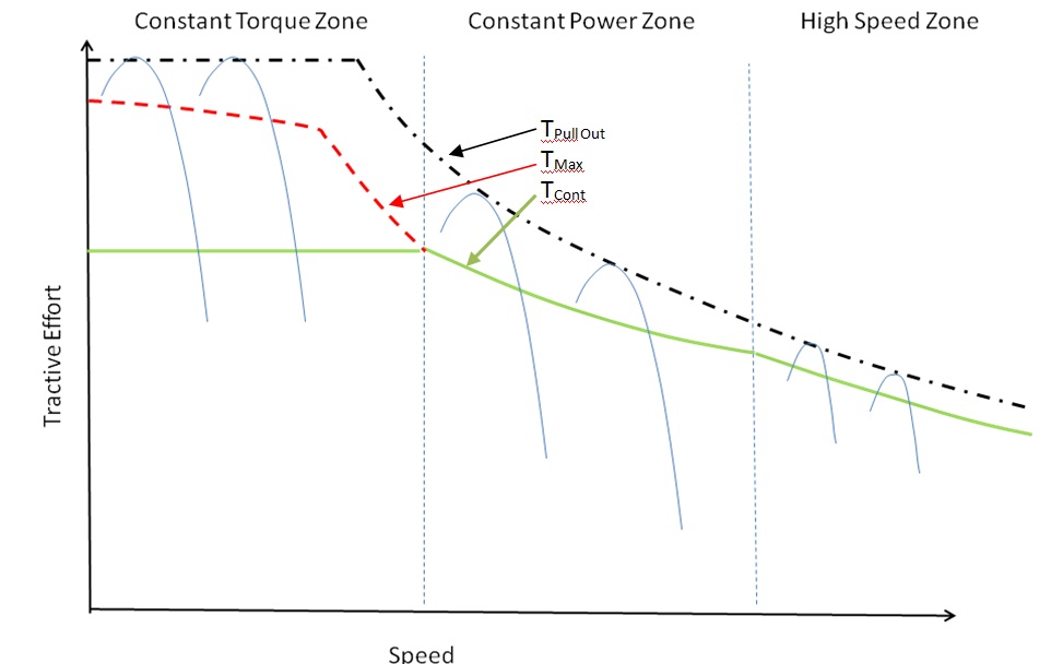
Constant Torque Zone
Now Ir∝fslΦag and Tem∝ΦagIr we get Tem∝(Φag)2fsl; from this equation it may be derived that if we keep the air gap flux at the maximum and constant along with fsl also constant, motor will deliver maximum torque and at constant level. Torque speed curve at different frequencies is shown below. Tmax is the maximum torque motor can deliver for a short period without increasing the maximum permissible temperature.
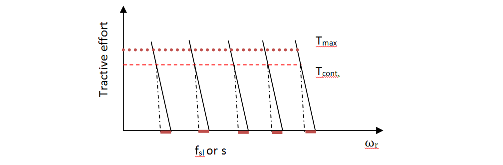
Constant Air gap Flux and Constant fsl = sf results constant torque up to rated frequency
Constant Power Zone
Φag can be maintained constant when voltage is increased in proportion to frequency. This is possible up to rated voltage thereafter, air gap flux reduces as indicated below
Φag=Eag/f; Tem∝(Φag)2fsl or Tem∝(Eag/f )2fsl or ∝Eag2fsl/f 2 or ∝ fsl/f 2 or ∝ sf/f 2 or ∝ s/f
It means torque varies inversely proportion to frequency by keeping slip constant.
Reduced Power Zone
Torque reduces with reduction of slip and therefore slip can only be reduced to the limit of minimum torque which is essentially required by load. Thereafter slip reduces in proportion to frequency, keeping sf constant and in this situation Tem is in inverse proportional to square of frequency.
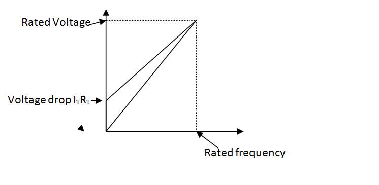
Voltage Boost at Low Voltage
Air gap flux is required to be maintained constant to derive constant tractive effort up to constant tractive effort zone of the drive. Voltage applied provides air gap flux as well as drop across stator resistance therefore voltage boost is required at low voltages to maintain constant air gap.
Vs = kf+ I1R1
The percentage I1R1 drop is significant at lower frequency operation therefore voltage boost is required to compensate for the voltage drop as shown below
Regenerative Braking
This is the most important feature of traction motor provides opportunity for saving on energy but also smoothness in braking, saving on wear and tear in mechanical braking system. An Induction motor works as a generator if mechanical speed is more than the synchronous speed. When called upon to brake, the frequency applied to the stator is lowered below the mechanical speed, and what happens is explained as follows:
A Traction motor is operated at frequency f0,Slip s0 and delivering torque τ0 shown on curve below. Now the frequency of the stater is reduced to f1, the demand of torque slip characteristics now shifts to curve B requiring point of operation shift. to curve B where torque and slip becomes negative and shifts to point B on the curve B with regeneration to start. Maximum value o regenerative tractive effort is limited to 25T and so is negative torque of the traction motor. The rate of change of frequency decides the maximum setting; voltage is simultaneously reduced along with frequency.
You may also like:
- Current Developments in the field of Traction motors
- Re-engineering of Stators of Three phase Traction Motors type 6FRA…
- Selection of Suspension Arrangement of Traction Motors : A Right…
- What is Electricity, Drift Velocity and Electric Current?
- Multiple Choice Question on Basic Concept of Science Class X…
- Selection of Suspension Arrangement of Traction Motors : A Right…
Very nice
With thanks
Articles good, but to explain effects of inductance and IR on three phase traction motors characteristics.Clear representation by representation is required.
Torque and three-phase power of traction must be high