Regeneration in Electric Locomotives with DC Traction Motors : A Strategic Domain
By: Mr R.N.Lal, Senior Executive Director Standards & Mr Ganesh, Director, Standards Electrical Directorate, Research Design and Standards Organisation , Lucknow
Introduction
Out of all modes of transportation system, only Indian Railways (IR) has been matching with the burgeoning growth of the economy of India by maintaining the unit price in spite of steep rise in fuel prices .To stay competitive, we have to develop creative solutions to cut down the expenditure on fuel . Worldwide , there is a trend to make railroad more energy-efficient. Understanding the significance of Rail Industry in US Economy ,US has laid down stress on energy efficiency in transportation. As a result, the railroads , their manufacturers and the federal government have embarked on a cooperative effort to further improve railroad fuel efficiency, i.e. 25% by 2010 and 50% by 2050. Some of the Fuel efficiency measures have already taken by US Rail road since 2005 and 16% of energy efficiency has been achieved so far. Among various other measures taken by US Railroad , energy recovery during braking is the most significant one.
Energy regenerated/recovered during braking is used – to meet hotel load requirement by storing it in super capacitor/batteries , to be used by other trains in the sections and to feedback to the national grid and take credit for the energy delivered. A study carried out by UIC suggests that all type of services, e.g. freight , passenger – suburban , mainline, intercity has potential of regenerating energy from 15% to 45% depending upon type of terrain/section,speed,etc, including DC traction.
Railways are the most efficient mode of transport in any country and electric traction is the most energy-efficient mode of traction. DC Electric traction on IR started in 1925 in Mumbai suburban area whereas 25KV 50Hz electric traction started in early 1960s with tap changer technology. IR has been manufacturing tapchanger locomotives till date which are still its workhorse .Over 3000 nos. of 25 KV AC 50Hz locomotives are in service on IR and will be serving for next two and half decades. All freight locomotives are provided with rheostat braking .All new passenger locomotives are also being manufactured with rheostat braking and there is drive to provide this type of braking in older locomotives also. In all these locomotives , energy during braking are not being recovered as these all are fitted with uncontrolled rectifier bridge to feed traction motors .
IR has acquired electric locomotives with three-phase technology in late 90s.These locomotives are capable of generating power during braking and draw traction power at unity power factor. Approximately , 15% energy is being regenerated in freight locomotives , 20% in passenger locos and 30% in EMUs. But such locomotives form only 6% of total locomotive holding and the rest of the locomotives are dissipating energy in resistance grid during braking. Energy to the tune of INR 18.75 billion is being lost during braking , if captured back , the same amount will saved on energy bill.
Because of converter inverter sets with microprocessor control , locomotives with three-phase technology are able to regenerate energy during braking. Now with advent in technology of power electronics, control electronics and higher density energy storage devices , it is possible to regenerate energy during braking back to the grid or use the regenerated energy for hotel load with high density energy storage devices.
IR can adopt microprocessor controlled IGBT based converter in place of existing tap changer and uncontrolled rectifier in huge fleet of DC traction motor fitted locomotives to regenerate braking energy. Such retro fitment , will not only feedback the energy recovered from braking , but will also have unity power factor operation , better slip slide control, constant speed control, less maintenance of locomotive and trailing stocks,etc. Energy regenerated can earn carbon credits under Kyoto Protocol.
Energy Recovery Opportunities:
UIC has carried out a detail study on Energy Regeneration in 25 KV 50Hz , 16 2/3 Hz and DC traction system on various types of train services. All these reports give the potential of energy regeneration depending upon type of terrain/section,speed,etc. in all the above traction systems , which is given below :
| Train Services | Energy Regeneration Opportunity |
| Main Lines | 15% |
| Regional Lines | 35% |
| Local Lines | 45% |
| Freight Lines | 20% |
In country like US , for making rail road more energy-efficient ,major area of research identified in the report of “Rail Road and Locomotive technology Roadmap” year 2002, prepared by Canter of Transportation Research Argonne National Laboratory , US Department of Energy are listed below :
- Train System: Operations Optimisation ,Consist Management , Aerodynamics , Wheel/Rail Friction and Rolling Resistance
- Locomotive System :Idle Reduction, Energy Recovery and Motors & Drives
- Locomotive Engines : High-efficiency Turbo, Sensors & Controls , Fuel Injection/Combustion , NOX Absorber ,PM Trap
- Advanced Power Plants and Fuels : Homogeneous Charge Compression Ignition , Alternate Fuels and Fuel Cells.
It can be seen from above that the Energy Recovery during braking is one of the key area of focus. With more diesel locomotives in service, if US Railroad can have an action plan for energy-saving to this extent, with more percentage of electric locomotives , we can save still more.
Exploiting Potential of Regenerative Braking on IR
Differential speeds of various types of train services leading to frequent braking for precedences or checks at signals ,undulating terrain of IR , ever-increasing demand of inter- city services with frequent stops and starts, energy regeneration potential is reasonably high , which can be substantiated with the energy regeneration figures of locomotives with three-phase traction motors. Now, we have to explore the develop the technology for capturing the braking energy of locomotives with DC traction motors.
Nevertheless, much of the potential is not exploited due to the following reasons:
- Except three-phase locomotives/EMUs, all other locomotives/EMU are not equipped with regenerative braking.
- Even in three-phase locomotives, the choice of the brake is up to the driver.
The future potential may be exploited by removing some of the present obstacles. This includes :
- Retro-fitment of the existing electric rolling stock of DC traction motor and tap changer technology with suitable power converter along with control electronics to recover braking energy through regeneration in place of existing reheostatic braking.
- Brake blending features i.e. favourable operational concepts ,so that maximum permitted use of regeneration brakes can be ensured. Typically brakes are blended, i.e. when the driver brakes, first the regenerative brakes are applied, if more power is needed (especially in unforeseen situations) additional brakes are applied.
- Migration towards EMUs or the concept of train sets. Generally, EMUs have a better regenerative braking performance than loco-hauled trains, since more axles are powered. The higher the motor power and the more axles are powered, the more energy may be recovered.
- Training programs and incentives for Loco Pilots
In the case of heavy freight trains only a small fraction of the kinetic energy can be recovered, since tractive force is supplied only by the locomotive and (mechanical) braking force is distributed along the entire train. The situation is somewhat improved in double traction, i.e. with a train hauled by two locomotives.
IR has provided energy meters which record energy consumed during the journey , regenerated back to the grid ,energy dissipated in resistance grid during braking and coasting time as it is always told that to conserve energy , first of all start measuring it.
It can be concluded that there is very high potential of energy saving on IR to the tune of 25% can be achieved for main line services and 30% on sub-urban services.
Energy Regeneration in Locomotives with DC Traction Motors
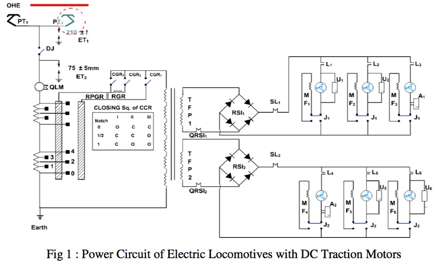
Schematic Diagram of power system layout from transformer to traction motor is given in Fig 1.Control of DC traction motors are through on load tap changer .Power after rectification is fed to traction motors. Rectifier used here uncontrolled and it is unidirectional ,i.e. it can only rectify power from AC to DC during traction and so no regeneration during braking is possible. During reheostatic braking, field coils of all six traction motors are connected in series whereas across each armature one braking resistance gets into the service. Kinetic energy of the train gets dissipated into resistance grids as heat energy which is in turn cooled by forced/natural air. If there is not enough electrical braking power, train is controlled with the help of pneumatic braking where heat is generated at wheels. In both the cases, the kinetic energy of the train is totally wasted.
Topology of Retrofits Converters for DC Traction Motors:
A study on Energy Efficiency Improvements to Electric Locomotives using PWM Rectifier Technology by F Finders and W Oghanna of Central Queensland University Australia. This study has suggested two topologies for Class 3100/3200 and Class 3500/3600 locomotives on Queensland Railways. These locomotives are having propulsion system with DC traction Motors supplied by Hitachi and ASEA, respectively. Queensland Railways, after detail analysis of PWM Controlled Rectifier Technology, has already entered into a contract with a leading locomotive manufacturer to retrofit their 60 nos. of Class 3100/3200 locomotives with AC Propulsion System in 2007 after initial successful prototype retro fitment of three number of Class 3100/3200 in March 2006.This project comprises of supply the complete electrical equipment comprising the drive units, converters, transformers, cooling systems, and driver’s cab electronics together with the related controls. Upgrading will increase the power rating, tractive effort and also the availability and reliability of these locomotives, which are to be used for transporting coal. It will also extend the service life of these units by 20 more years.
High power regenerative PWM DC Motor drives have been developed. It is expected that the power converter system would be a novel combination of existing topologies utilising state- of-the art microprocessor and digital signal processing control system technology. Many topologies for converter-chopper can be possible, however, now there are two converter configurations under consideration and these are – a) the voltage sourced PWM rectifier cascaded with a two quadrant buck converter chopper and b) the current sourced PWM rectifier.
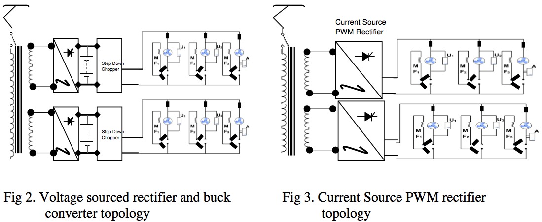
The voltage sourced rectifier and buck converter :
The proposed topology is shown in Fig.2 The converter section consisting of L, C and IGBT bridge is similar to what is found in many of the modern AC motor traction drive system with boost converter , which maintains DC output voltage always above the peak source voltage. In practice, it would be normally be set at least 30% higher. After DC link, controlled DC supply is fed to the set of three traction motors during traction mode .During braking , with suitable arrangement of configuration contactors , field coils of three traction motors a bogie get in series and will separate supply from transformer winding and all TMs regenerates energy through the chopper and inverter back to the OHE with the help of suitable control electronics.
The possibility exists to divide a single lower powered chopper to each of the traction motor in a multi-motor configuration. This would give scope for improved wheel –slip control performance.
Current source PWM rectifier configuration
The current source PWM rectifier configuration ( Fig.3) is derived from the basic buck converter and so capable of voltage reduction. This makes it suitable as a DC Motor drive. Essentially , it is the ‘Dual” of the voltage sourced converter. This means that series inductor becomes shunt capacitors and shunt capacitors becomes series inductors. Voltage sources become current sources and vice-versa.
The switching configuration is based on the requirement of voltage amplitude and waveform . The current sourced converter therefore has a shunt capacitor at its input and a series inductor in its output. For the voltage sourced converter the current is controlled by the difference in voltages across a series inductance. For the current sourced converter the input voltage is controlled by the difference in currents flowing through a shunt capacitor. This then requires
he supply to be a current source. However the current source may be replaced by a voltage source in series with an inductance. A suitable control system controls the input current by manipulation of the capacitor voltage which in turn is manipulated by the converter PWM switching. This configuration makes the system behave much the same as if the input was a current source. The current sourced converter is capable of reverse power flow. The buck derived current source converter is capable of controlling the motor armature current and therefore the tractive effort through its required range. However to get braking effort it is required to reverse the armature voltage. This may he achieved by reversal of the field current. The armature current remains in the same direction.
Retro fitment on Existing Locomotives
Topologies explained above are just illustrative as all the leading manufacturers of electric locomotives are having their state of the art converter solutions along with control electronics. Their assistance can be sought to make a tailor made solution for these locomotives. A suitable converter along with its control system can be provided across each secondary winding of the transformer ,depending upon the fact ,if we want bogie control or individual motor control. A central electronics will take the command from master controller from loco pilot ,i..e. for traction or braking and according converter will assume the role of a controlled rectifier and inverter. Excitation of field windings will be taken care of separately during braking.
Such arrangement will cut a number of maintenance intensive equipment: such as tap changer , SMGR, reversers , CTFs, MVRF and DBR units ,etc. The work can be taken up during MTR of locomotives which can enhance not only the working life of the locomotive , but will make the locomotive more energy efficient with a payback period of only 5-6 years.
Conclusion
To recover energy during braking , worldwide Railways are in the process of upgrading their existing fleet of locomotive with DC traction motors with AC propulsion system along with suitable control system .Already , work is progress in Queensland Railway and New Zealand Railways. To capture the huge potential of braking energy on IR, suitable action plan is required to be made to retrofit existing fleet of over 3000 locomotives with PWM converter. As per UIC report , normally the pay back period for such project is 5 to 6 years. Since leading locomotive manufacturers are getting into this business , their ability can be sought for IR , also. This concept can be extended to huge fleet of AC EMU/MEMU where potential of energy regeneration is much higher. To start with , a pilot project can be taken to retrofit few EMU/MEMU rakes , where energy regeneration potential is greatest.
References
- Railroad and Locomotive Technology Roadmap ,Center for Transportation Research ,Argonne National Laboratory ,Operated by The University of Chicago,for the United States Department of Energy.
- Flinders, F.; Oghanna, W. -Energy efficiency improvements to electric locomotives using PWM rectifier technology , Electric Railways in a United Europe, 1995., International Conference on Volume , Issue , 27-30 Mar 1995 Page(s):106 – 110
- Flinders, F.; Mathew, R.; Oghanna, W. , Energy savings through regenerative braking using retrofit converters ,Railroad Conference, 1995., Proceedings of the 1995,IEEE/ASME,Joint Volume , Issue , 4-6 Apr 1995 Page(s):55 – 61
- Hill, R.J. – Electric railway traction. I. Electric traction and DC traction motor drives ,Power Engineering Journal [see also Power Engineer] Volume 8, Issue 1, Feb 1994 Page(s):47 – 56
- Glinka, M. – Member, IEEE ,Institute of Power Electronics and Control ,Universität der Bundeswehr München, Germany – Prototype of Multiphase Modular-Multilevel- Converter with 2MW power rating and 17-level-output-voltage
- Jorgensen, A.A, – RailRoad Association of South Africa.-The Regeneration Of Railways In South Africa and intermodal opportunities for the road transport sector
- Y uruki Okada, T akafumi Koseki, Kohei Hisatomi ,The University of T okyo, Japan ,Shin-Keisei Electric Railway, Japan- Power Management Control in DC-electrified Railways for Regenerative Braking Systems of Electric Trains
- UIC Reports on – Regenerative braking in 16,7 Hz, 15 kV systems , Regenerative braking in 50 Hz, 25 kV systems , Regenerative braking in DC systems , Regenerative braking in freight trains
Short Biographies of Authors:
Mr R.N.Lal, is an officer of Indian Railway Services of Electrical Engineers of 1974 examination and has graduated from Institute of Technology, Banaras Hindu University, Banaras and has done his post graduation in Control Systems Engineering from the same University. He has varied experience in the field of maintenance, operation and designing of rolling stock and traction installation. He has worked in various capacities all over India Railways including Additional Railway Manager/Kota and Divisional Railway Manager/Asansol and Sr.Deputy General Manager, North Eastern Railway, Gorakhpur. Presently, he is working as Sr.Executive Director Standards of Electric Loco Directorate of Research Designs and Standards Organisation (RDSO), Lucknow, India since June 2007.
Mr Ganesh, joined Indian Railway Services of Electrical Engineers 1991 exam batch after obtaining B.Tech in Electrical Engineering from REC,Warangal . He has rich experience in various fields of Electric Locomotives. He has worked at Electric Loco Sheds at Gomoh, Asansol and Kanpur. At present, he is working as Director Standards Electrical, at Research Designs and Standards Organisation (RDSO), Lucknow, India since May’2007.
You may also like:
- What is Electricity, Drift Velocity and Electric Current?
- Re-engineering of Stators of Three phase Traction Motors type 6FRA…
- How a locomotive works a train?
- Multiple Choice Question on Basic Concept of Science Class X…
- Weight Transfer during Braking
- Selection of Suspension Arrangement of Traction Motors : A Right…
I have noticed you don’t monetize your site, don’t waste your traffic, you
can earn additional cash every month because you’ve got high quality
content. If you want to know how to make extra
bucks, search for: Mertiso’s tips best adsense alternative
I have a question for you about earthing/grounding of 2ry part of the traction circuit transformer. I think these 2ry part including converter/inverter/motor shall not be earthed/grounded. Is it correct?